Verilog Code For Serial Adder Table
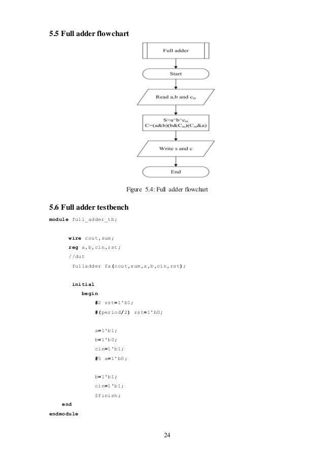
Apr 30, 2014. Nov 06, 2016. Also see-Full adder by calling half adder Full adder is a combinational arithmetic logic circuit that adds three numbers and produces a sum bit (S) and carry bit (C) as the output. This site was designed with the.
Contents • • • • • • • • • • • • • • • Full-Adder in Verilog Review A full adder is a combinational logic that takes 3 bits, a, b, and carry-in, and outputs their sum, in the form of two bits, carry-out, and sum. The figure below illustrates the circuit: New Project • The first task is start the Xilinx ISE and create a New Project. Let's call it FourBitAdder. Vis Radom Serial Numbers. • Once the Project is created, add a New Source, of type Verilog Module.

Verilog Code For Serial Adder Tables
Call it SingleStage. It will contain the full-adder for 2 bits. • Define the ports as follows: • a, input • b, input • cin, input • s, output • cout, output We now have several options to define this adder. Fl Studio 11 Reg Key File Download. One is functional, as illustrated in the next subsection. Next is a logical description, where we express the outputs in terms of their logical equation.
Verilog Half Adder
The final is a gate level description. Pick the one that seem most interesting to you.